CAN interfaces · Datasheet
SPI-CAN Breakout Rev A
Breadboard-friendly CAN FD breakout for SPI hosts
Features
- Miniature breadboard-compatible footprint for quick prototyping
- SPI host interface for Classic CAN and CAN FD via the MCP2518FD controller
- Switch selectable bus termination (split 2x 60 Ohm + centre-tap capacitor)
- Jumper selectable 5 V or 3.3 V logic level for the host interface
- Jumper selectable silent mode (listen-only) for bus monitoring
- 1x M2.5 mounting hole
Overview
A small-footprint, breadboard-friendly breakout board that bridges an SPI host to a CAN bus. It exposes a standard SPI interface on one side and a CAN transceiver on the other, letting any microcontroller with SPI talk CAN without an integrated controller.
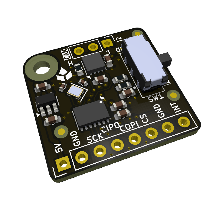
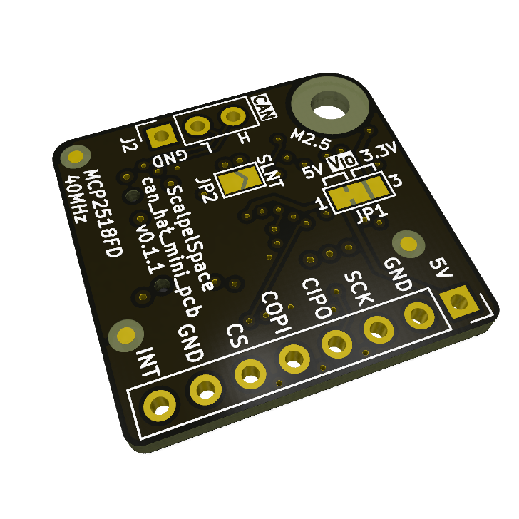
Specifications
| Parameter | Conditions | Min | Typ | Max | Unit |
|---|---|---|---|---|---|
| Power | |||||
| Supply voltage | 5V pin | 5.0 | V | ||
| Logic level | 5 V (default) or 3.3 V (JP1) | ||||
| Host interface | |||||
| Interface | SPI | ||||
| CAN | |||||
| Controller | MCP2518FD, 40 MHz crystal | ||||
| Transceiver | TJA1057BTK | ||||
| Bus termination | Switch selectable 120 Ohm, split 2x 60 Ohm + centre-tap capacitor (SW1) | ||||
| Mechanical | |||||
| Form factor | Breadboard-compatible breakout | ||||
Connectors and pinout
| Ref | Connector | Description |
|---|---|---|
J1 | 8-pin | Host interface header (power and SPI). |
J2 | CAN | CAN bus connection. |
J1: 8-pin
| Pin | Name | Type | Description |
|---|---|---|---|
1 | 5V | PWR | 5 V supply |
2 | GND | PWR | Ground |
3 | SCK | IN | SPI clock |
4 | CIPO | OUT | SPI controller in, peripheral out |
5 | COPI | IN | SPI controller out, peripheral in |
6 | CS | IN | SPI chip select |
7 | GND | PWR | Ground (optional second ground) |
8 | INT | OUT | Controller interrupt |
J2: CAN
| Pin | Name | Type | Description |
|---|---|---|---|
1 | GND | PWR | Ground |
2 | CANH | IO | CAN high |
3 | CANL | IO | CAN low |
Switches and jumpers
| Ref | Function | Settings |
|---|---|---|
SW1 | CAN termination | 1 + 2 = no termination, 2 + 3 = 120 Ohm termination |
JP1 | V IO | 1 + 2 closed = 5 V, 2 + 3 closed = 3.3 V |
JP2 | CAN silent | Open = normal operation, closed = silent mode |
Detailed description
Host interface
The 8-pin header (J1) carries 5 V power, ground and the SPI lines (SCK, CIPO, COPI and CS) of the MCP2518FD controller. The second ground pin is optional.
The interrupt pin (INT) is optional but recommended. It should be attached to a hardware interrupt pin on the host.
Logic level
The V IO jumper (JP1) selects the logic level of the host interface: 5 V (default) or 3.3 V. Set it to match the host.
Bus termination
The CAN termination switch (SW1) connects a 120 Ohm split termination (2x 60 Ohm with a centre-tap capacitor) across the bus. The switch positions are marked 120 (terminated) and NC (not terminated).
Enable termination only when the board sits at a physical end of the bus.
Silent mode
Closing the CAN silent jumper (JP2) puts the transceiver in silent (listen-only) mode, for monitoring a bus without transmitting on it.
Firmware and software
Firmware and software are maintained and documented in their own repositories.
| Repository | Type | Description |
|---|---|---|
| scalpelspace_bus | Arduino library | ScalpelSpace unified CAN ID allocation scheme and device control. |
Key components
| Part number | Manufacturer | Description | Qty |
|---|---|---|---|
MCP2518FDT-E/QBB | Microchip Technology | CAN FD to SPI controller | 1 |
TJA1057BTK | NXP USA Inc. | CAN bus transceiver | 1 |
JS202011JAQN | C&K | DPDT slide switch, right angle | 1 |
ECS-400-10-37B2-CKY-TR | ECS Inc. | 40 MHz crystal | 1 |
Mechanical
Design files
Errata
No known errata for Rev A.
Revision history
| Revision | Released | Status | Changes |
|---|---|---|---|
| Rev A | 2026-05-03 | Active |
|