Motor control · Datasheet
MC Stepper Rev A
Closed-loop stepper motor controller
Features
- Closed-loop position and velocity control via the AS5147P 14-bit magnetic rotary encoder
- Bipolar stepper motor driver via the TMC2209, with runtime configurable current and microstep resolution
- StallGuard stall detection with configurable threshold
- Classic CAN (500 kbps) host interface with dynamic node ID allocation, driven by an STM32L432KC
- Single power and CAN connector, up to 29 V input
- UART serial interface for development, debug and configuration, plus SWD via Tag-Connect
- GPIO connector with 3.3 V supply for custom hardware
- Addressable RGB LED (WS2812B-2020) for status display
Overview
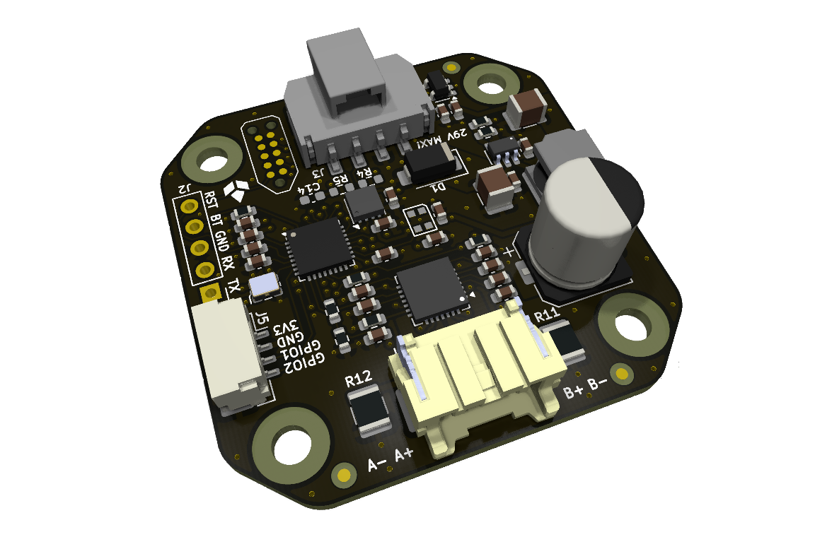
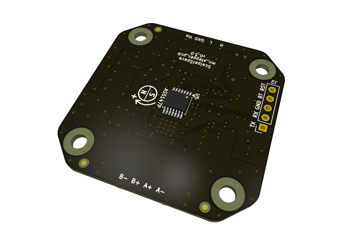
A compact stepper motor controller node that bridges a CAN bus host to a bipolar stepper motor. It pairs a TMC2209 motor driver with an AS5147P magnetic rotary encoder for closed-loop position and velocity control, letting a single CAN bus drive and monitor multiple motors.
Specifications
| Parameter | Conditions | Min | Typ | Max | Unit |
|---|---|---|---|---|---|
| Power | |||||
| Supply voltage | VIN | 6 | 12 | 29 | V |
| GPIO 3.3 V output | Approximate, thermally limited | 200 | mA | ||
| Host interface | |||||
| Interface | Classic CAN, UART serial for debug | ||||
| CAN | Classic CAN, 500 kbps (87.5% sample point) | ||||
| Bus termination | Optional split 2x 60 Ohm + 4.7 nF, not populated (R4, R5, C14) | ||||
| UART | USART1, 115200 bps, 3.3 V logic | ||||
| Devices | |||||
| Motor driver | TMC2209 driver | ||||
| Encoder | AS5147P absolute magnetic | ||||
| Mechanical | |||||
| Form factor | NEMA 17 back plate-style | ||||
Connectors and pinout
| Ref | Connector | Description |
|---|---|---|
J1 | Tag-Connect TC2050 | SWD programming/debug connector. |
J2 | UART breakout | 1x5, 2.54 mm pitch. Serial interface and UART bootloader control. |
J3 | Power and CAN | 1x4 Molex Nano-Fit, 2.5 mm pitch. Supply input and CAN bus. |
J4 | Motor | 1x4 JST PA, 2 mm pitch. Bipolar stepper motor coils. |
J5 | GPIO | 1x4 JST GH, 1.25 mm pitch. Custom hardware connections. |
J2: UART breakout
| Pin | Name | Type | Description |
|---|---|---|---|
1 | USART1_TX | OUT | UART transmit |
2 | USART1_RX | IN | UART receive |
3 | GND | PWR | Ground |
4 | BOOT0 | IN | Assert high to enter the bootloader on reset |
5 | NRESET | IN | STM32 reset |
J3: Power and CAN
| Pin | Name | Type | Description |
|---|---|---|---|
1 | CANH | IO | CAN high |
2 | CANL | IO | CAN low |
3 | GND | PWR | Ground |
4 | VIN | PWR | Supply input, 29 V maximum |
J4: Motor
| Pin | Name | Type | Description |
|---|---|---|---|
1 | A+ | OUT | Coil A positive |
2 | A- | OUT | Coil A negative |
3 | B+ | OUT | Coil B positive |
4 | B- | OUT | Coil B negative |
J5: GPIO
| Pin | Name | Type | Description |
|---|---|---|---|
1 | 3V3 | PWR | 3.3 V LDO output, approximately 200 mA available |
2 | GND | PWR | Ground |
3 | GPIO1 | IO | General purpose I/O |
4 | GPIO2 | IO | General purpose I/O |
Indicators, test pads and battery
LEDs
| LED | Marking | Description |
|---|---|---|
| WS2812B-2020 LED | None | RGB addressable LED |
Detailed description
Power supply
The board is powered through the Power and CAN connector (J3). The maximum input voltage is 29 V, limited by the absolute maximum supply rating of the TMC2209. Operating below this limit (28 V or less) is recommended for margin.
GPIO connector
The GPIO connector (J5) is intended for custom hardware connections. The 3.3 V pin is supplied by the onboard TLV77333PDBVR LDO (300 mA maximum). Onboard circuitry is budgeted at 100 mA, leaving approximately 200 mA available for external hardware. Actual available current may be limited by LDO thermal dissipation, depending on input voltage and ambient temperature.
On-board CAN termination
R4, R5 and C14 are not populated by default. They are reserved for optional on-board split termination: two 60 Ohm resistors with a 4.7 nF capacitor from their midpoint to ground.
Populate these components only when the board sits at a physical end of the CAN bus.
STM32L432KC flashing
The STM32L432KC can be flashed in two ways:
- SWD via the Tag-Connect TC2050 connector (J1).
- UART bootloader via the
UART breakoutconnector (J2): assertBOOT0(pin 4) high and pulseNRESET(pin 5) to enter the bootloader.
Firmware and software
The mc_stepper firmware supports both the AS5047P and AS5147P encoders (source files keep the "AS5047P" naming). Flash over the UART bootloader or over SWD (see Detailed description).
Firmware and software are maintained and documented in their own repositories.
| Repository | Type | Description |
|---|---|---|
| mc_stepper | Firmware | Official STM32L432KC firmware, configuration macros and UART command reference. |
| mc_stepper_driver | Driver | Host driver (CAN), source-of-truth DBC definition and message table. |
| scalpelspace_bus | Arduino library | Arduino library (CAN). |
Protocols: ScalpelSpace CAN Protocol
Key components
| Part number | Manufacturer | Description | Qty |
|---|---|---|---|
STM32L432KC | STMicroelectronics | 32-bit MCU | 1 |
TMC2209 | Analog Devices Inc./Maxim Integrated | Bipolar motor driver | 1 |
AS5147P | ams-OSRAM USA INC. | Magnetic rotary encoder | 1 |
TJA1057BTK | NXP USA Inc. | CAN bus transceiver | 1 |
LMR51610XDBVR | Texas Instruments | 5 V buck converter | 1 |
TLV77333PDBVR | Texas Instruments | 3.3 V LDO (300 mA) | 1 |
WS2812B-2020 | (Various) | PWM addressable RGB LED | 1 |
Mechanical
Design files
Errata
No known errata for Rev A.
Revision history
| Revision | Released | Status | Changes |
|---|---|---|---|
| Rev A | 2026-09-21 | Pre-production |
|