Sensors · Datasheet
Momentum Rev A
GNSS, 9-DOF IMU and barometer sensor shield
Features
- 9-DOF IMU via the BNO085
- Multi-constellation GNSS via the SAM-M10Q
- 24-bit barometric pressure sensor via the BMP390
- SPI or Classic CAN host interface, driven by an STM32L432KC sensor hub
- USB-C serial interface (CP2102N) for firmware update, plus SWD via Tag-Connect
- Addressable RGB LED (WS2812B)
- Dual 5 V source (5V pin or USB-C) with automatic switching
- Jumper selectable 5 V or 3.3 V logic level on the SPI interface
Overview
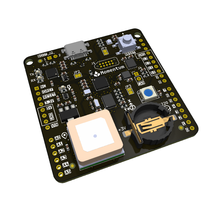
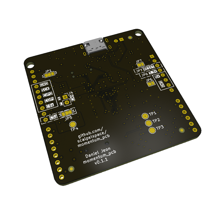
A Uno-style footprint sensor integration board that bridges an SPI or CAN host to sensor telemetry. It combines a 9-DOF IMU, multi-constellation GNSS and a barometric pressure sensor on a single board, allowing rapid integration of a full sensor suite into any project with an SPI or CAN bus host controller.
Specifications
| Parameter | Conditions | Min | Typ | Max | Unit |
|---|---|---|---|---|---|
| Power | |||||
| Supply voltage | 5V pin or USB-C | 5.0 | V | ||
| Supply current | All sensors on | 30 | 300 | mA | |
| 5 V source selection | Automatic OR switch, 5V pin has priority | ||||
| 5V pin protection | None | ||||
| 3.3 V rail | Onboard LDO, optional output on the 3.3V pin (JP6) | ||||
| Host interface | |||||
| Interface | Classic CAN, SPI or Serial | ||||
| CAN | Classic CAN (default 500 kbps) onboard termination | ||||
| SPI logic level | 5 V (default) or 3.3 V (JP1) | ||||
| SPI CS pin | D10 (default) or D8 (JP5) | ||||
| USB | USB-C, CP2102N USB-to-UART bridge | ||||
| Devices | |||||
| IMU | BNO085 | ||||
| GNSS module | SAM-M10Q | ||||
| Barometer | BMP390 | ||||
| Mechanical | |||||
| Form factor | Uno-style shield | ||||
Connectors and pinout
| Ref | Connector | Description |
|---|---|---|
J1 | Tag-Connect TC2050 | SWD programming/debug connector. |
J2 | BOOT0 jumper | Through-hole jumper. Open = run from flash memory (pull-down on open), bridged = assert BOOT0. |
J3 | USB-C | USB-to-serial programming/debug, secondary 5 V source. |
J4 | CAN1 | CAN bus connection. |
Uno | Uno-style headers | Host interface: SPI (level shifted), 5 V supply input, optional 3.3 V and reset outputs. |
J4: CAN1
| Pin | Name | Type | Description |
|---|---|---|---|
1 | CANH | IO | CAN1 high |
2 | CANL | IO | CAN1 low |
Uno: Uno-style headers
| Pin | Name | Type | Description |
|---|---|---|---|
D13 | SCK | IN | SPI clock |
D12 | CIPO | OUT | SPI controller in, peripheral out |
D11 | COPI | IN | SPI controller out, peripheral in |
D10 | CS1 | IN | SPI chip select (default, JP5 1 + 2) |
D8 | CS2 | IN | Alternative SPI chip select (JP5 2 + 3) |
5V | 5V | PWR | Primary 5 V supply input (priority over USB-C) |
3.3V | 3V3 | PWR | Optional 3.3 V LDO output (JP6 closed) |
RESET | NRST | IO | Optional STM32 NRST connection (JP7 closed) |
Switches and jumpers
| Ref | Function | Settings |
|---|---|---|
SW1 | Sensor hub MCU reset button | Generic 6 mm TH button, push to reset |
JP1 | Level shifter V IO | 1 + 2 closed = 5 V, 2 + 3 closed = 3.3 V |
JP2 | BOOT0 DTR bridge | Closed = CP2102N DTR BOOT0 control, open = manual BOOT0 |
JP3 | BNO085 clock select | Open = crystal, closed = external/internal |
JP4 | BMP390 I2C address | Open = 0x76, closed = 0x77 |
JP5 | Interface SPI CS pin select | 1 + 2 closed = CS1 (D10), 2 + 3 closed = CS2 (D8) |
JP6 | Interface 3.3 V output | Open = no output, closed = 3.3 V LDO output bridged |
JP7 | Interface NRESET output | Open = no output, closed = STM32 NRST bridged |
Indicators, test pads and battery
Test pads
| Ref | Net | Description |
|---|---|---|
TP1 | GPS NRST | u-blox GPS NRST net |
TP2 | GPS RX | u-blox GPS RX net |
TP3 | GPS TX | u-blox GPS TX net |
TP4 | WS2812B LED PWM | DOUT from onboard WS2812B |
Batteries
| Ref | Battery | Description |
|---|---|---|
BT1 | CR1220 battery cell | u-blox GPS RTC and ephemeris RAM |
Detailed description
Power supply
The board can be powered by either of the following methods:
5Vpin via the Uno-style interface.- Onboard USB-C connector.
The 5 V supply is managed by an OR power switch (TPS2116DRL). The 5V pin from the Uno-style interface takes priority: as long as ~1 V or more is present on this pin, it is used as the power source. Otherwise the board automatically switches to the USB-C 5 V supply.
The 3.3 V supply is managed onboard by a dedicated 5 V to 3.3 V LDO, independent of any connected board.
To use the board’s 3.3 V supply for low current applications, bridge the Interface 3.3 V output jumper (JP6). This connects the onboard LDO to the Uno-style interface 3.3V pin. Use with caution: a connected main controller usually supplies its own 3.3 V on the same pin.
SPI interface
All SPI pins interfacing with connected boards are level shifted. By default the external SPI pins are shifted to 5 V. They can be shifted to 3.3 V instead with the Level shifter V IO 3-pad jumper (JP1).
The SPI CS pin can be swapped between the Uno-style interface pins D10 (default) and D8 with the Interface SPI CS pin select jumper (JP5). This is intended to help resolve pin conflicts.
STM32L432KC flashing
The STM32L432KC can be flashed in 3 different ways:
- SWD via the Tag-Connect TC2050 interface (J1).
- Hands-free UART bootloader via USB-C (CP2102N USB-to-UART).
- Manual BOOT0 jumper with UART bootloader via USB-C (CP2102N USB-to-UART).
For the USB-C UART bootloader interface, the flashing web app blasher.scalpelspace.com is highly recommended.
All three options are available by default, however options 1 and 2 are suggested.
Option 3 applies when USB-C is used as both a serial and a UART bootloader interface. In this method the through-hole BOOT0 jumper (J2) must be manually bridged to assert BOOT0. See USB-C serial interface below.
USB-C serial interface
The USB-C interface, connected through the CP2102N USB-to-UART bridge, is primarily a UART bootloader flashing interface. It can also be used as a serial interface for simple communication with a desktop computer.
Because of the hands-free flashing design, the STM32’s BOOT0 is controlled by the CP2102N’s DTR pin. When a COM port is established, BOOT0 is raised high and the MCU enters the bootloader. To prevent this, cut the BOOT0 DTR bridge jumper (JP2), which allows USB-C serial communication.
With this modification the UART bootloader can still be used, but BOOT0 must be asserted manually with the through-hole BOOT0 jumper (J2).
Firmware and software
The momentum firmware supports this revision. Flash over USB-C with blasher or over SWD (see Detailed description).
Firmware and software are maintained and documented in their own repositories.
| Repository | Type | Description |
|---|---|---|
| momentum | Firmware | Official STM32L432KC firmware. |
| blasher.scalpelspace.com | Web app | In-browser firmware flashing over the STM32 UART bootloader and a serial monitor. |
| momentum_driver | Driver | Host driver (SPI/CAN). |
| scalpelspace_momentum | Arduino library | Arduino library (SPI). |
| scalpelspace_bus | Arduino library | Arduino library (CAN). |
Protocols: ScalpelSpace CAN Protocol
Key components
| Part number | Manufacturer | Description | Qty |
|---|---|---|---|
STM32L432KC | STMicroelectronics | 32-bit MCU | 1 |
CP2102N-A02-GQFN24R | Silicon Labs | USB 2.0 to UART interface | 1 |
BNO085 | CEVA Technologies, Inc. | 9-DOF IMU | 1 |
BMP390 | Bosch Sensortec | Barometric pressure sensor | 1 |
TJA1057BTK | NXP USA Inc. | CAN bus transceiver | 1 |
SAM-M10Q | u-blox | RF receiver Galileo, GLONASS, GPS | 1 |
WS2812B | (Various) | PWM addressable RGB LED | 1 |
TPS2116DRL | Texas Instruments | 5 V power OR switch | 1 |
TPD2EUSB30 | Texas Instruments | USB ESD protection | 1 |
Mechanical
Design files
Errata
No known errata for Rev A.