Tools · Datasheet
Blasher Rev A
USB-C firmware flash and utility tool
Features
- USB-C to UART bridge via the CP2102N
- Standard 5-pin UART breakout with
BOOT0andNRESETfor UART bootloader flashing - Switchable DTR control of BOOT0 for automatic bootloader entry
- In-browser firmware flashing and serial monitor with the Blasher web app
- NRESET button for manual target reset
- 3.3 V logic, from an onboard LDO
- RX, TX and power status LEDs
- USB ESD protection (USBLC6-2P6)
Overview
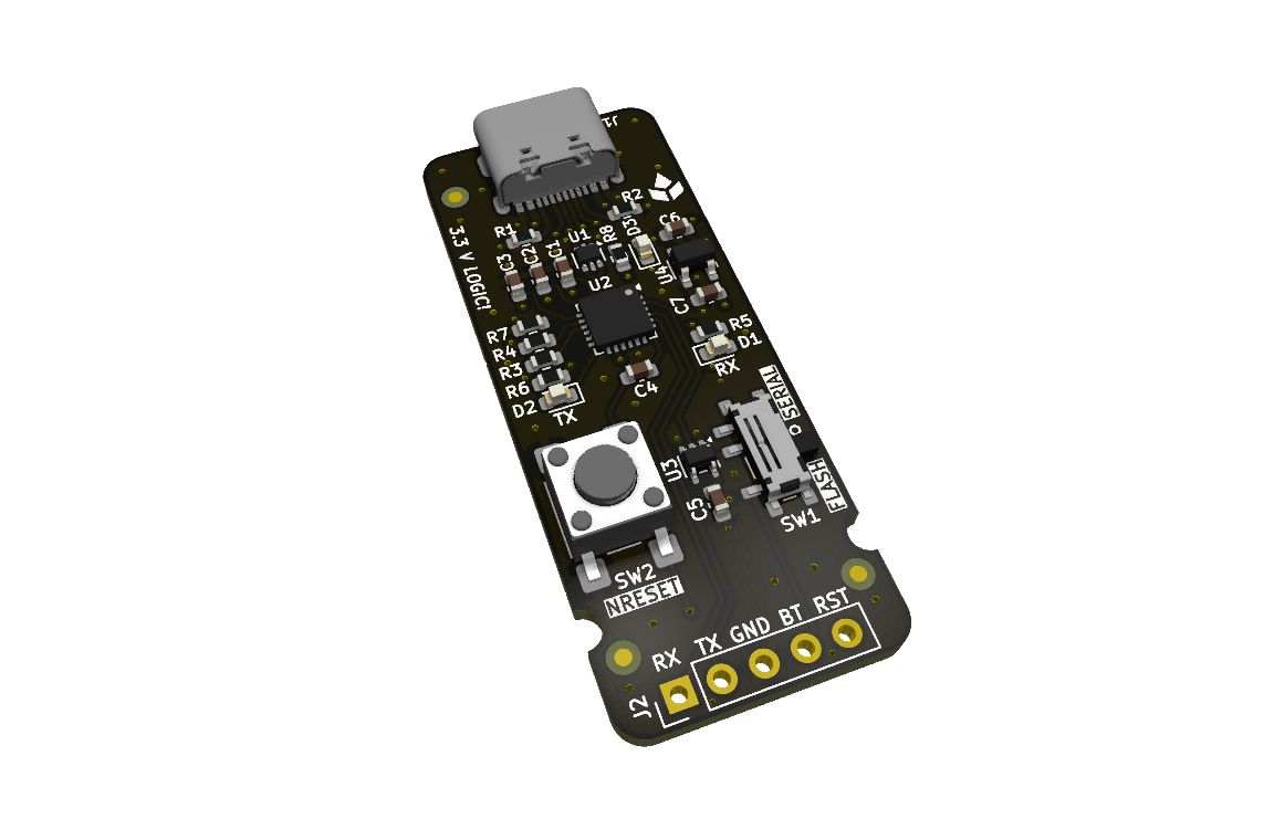
A basic firmware flash and utility tool. It bridges a USB-C host to the standard ScalpelSpace 5-pin UART breakout through a CP2102N USB-to-UART bridge, with BOOT0 and NRESET control for entering a target’s UART bootloader. Built for use with the Blasher web app at blasher.scalpelspace.com.
Specifications
| Parameter | Conditions | Min | Typ | Max | Unit |
|---|---|---|---|---|---|
| Power | |||||
| Supply | 5 V from USB-C | ||||
| 3.3 V rail | Onboard LDO (TLV77133) | ||||
| Logic level | 3.3 V | ||||
| Host interface | |||||
| USB | USB-C | ||||
| USB-to-UART | CP2102N (requires the Silicon Labs CP210x VCP driver) | ||||
| Target interface | |||||
| Connector | 5-pin UART breakout, 2.54 mm pitch | ||||
| Bootloader entry | BOOT0 via CP2102N DTR (SW1), NRESET button (SW2) | ||||
Connectors and pinout
| Ref | Connector | Description |
|---|---|---|
J1 | USB-C | USB-to-serial programming/debug, 5 V supply input. |
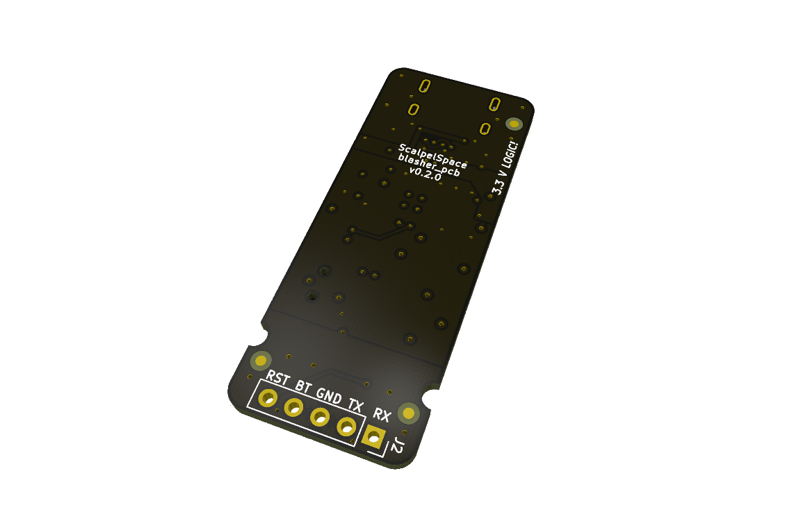
J2 | UART breakout | 1x5, 2.54 mm pitch. Connects to the target's UART breakout, pin for pin. |
J2: UART breakout
| Pin | Name | Type | Description |
|---|---|---|---|
1 | USART1_TX | IN | Target UART transmit |
2 | USART1_RX | OUT | Target UART receive |
3 | GND | PWR | Ground |
4 | BOOT0 | OUT | Target BOOT0 |
5 | NRESET | OUT | Target reset |
Switches and jumpers
| Ref | Function | Settings |
|---|---|---|
SW1 | BOOT0 DTR bridge | Closed = CP2102N DTR BOOT0 control, open = manual BOOT0 |
SW2 | NRESET button | Push to set NRESET low |
Indicators, test pads and battery
LEDs
| LED | Marking | Description |
|---|---|---|
| UART RX | Silkscreen "D1 RX" | Amber LED: blinking = receiving data |
| UART TX | Silkscreen "D2 TX" | Green LED: blinking = transmitting data |
| 3.3 V power | Silkscreen "D3" | Amber LED: on = 3.3 V net high |
Detailed description
Blasher web app
The main tool for Blasher is the web app at blasher.scalpelspace.com. It runs in the browser and talks to the board over its USB serial port, with two functions:
- Firmware flash: drop in a
.binimage for hands-free flashing over the target’s STM32 UART bootloader, with options to mass erase first, verify after write and run the application when done. - Serial monitor: a simple serial terminal for quick debugging.
Blasher does not power the target. The target must be powered separately.
USB interface via CP2102N
The USB interface uses a CP2102N USB-to-UART bridge, which requires Silicon Labs’s CP210x USB to UART Bridge VCP Drivers on the host.
Firmware and software
Blasher carries no firmware of its own. Use it with the Blasher web app (see Detailed description), which flashes a target over the STM32 UART bootloader and provides a serial monitor.
Firmware and software are maintained and documented in their own repositories.
| Repository | Type | Description |
|---|---|---|
| blasher.scalpelspace.com | Web app | In-browser firmware flashing over the STM32 UART bootloader and a serial monitor. |
Key components
| Part number | Manufacturer | Description | Qty |
|---|---|---|---|
CP2102N-A02-GQFN24 | Silicon Labs | USB 2.0 to UART interface | 1 |
USBLC6-2P6 | STMicroelectronics | USB ESD protection | 1 |
TLV77133PDBVR | Texas Instruments | 3.3 V LDO | 1 |
SN74LVC1G04DCK | Texas Instruments | DTR inverter | 1 |
2171790001 | Molex | USB-C receptacle | 1 |
Mechanical
Design files
Errata
No known errata for Rev A.
Revision history
| Revision | Released | Status | Changes |
|---|---|---|---|
| Rev A | 2026-09-21 | Preview |
|