Table of Contents
1 Overview
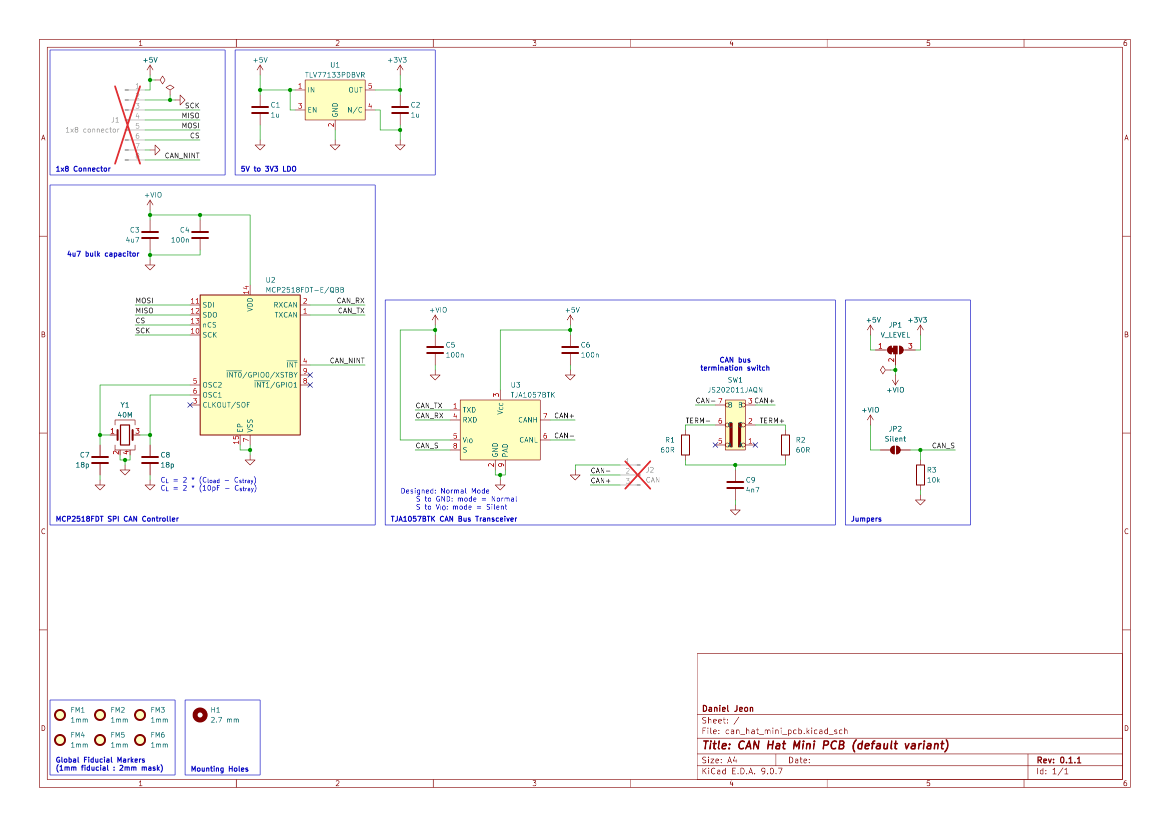
1.1 Bill of Materials (BOM)
| Manufacturer Part Number | Manufacturer | Description | Quantity | Notes |
|---|---|---|---|---|
| MCP2518FDT-E/QBB | Microchip Technology | CAN FD to SPI Controller | 1 | |
| TJA1057BTK | NXP USA Inc. | CAN Bus Transceiver | 1 | |
| JS202011JAQN | C&K | DPDT Slide Switch Right Angle | 1 | |
| ECS-400-10-37B2-CKY-TR | ECS Inc. | 40 MHz crystal | 1 |
2 Board Specifications
2.1 Connectors
Connectors fixed by hardware (PCB traces or the connector itself).
| Connector | Ref | Description |
|---|---|---|
8-pin | J1 | Pin 1: 5V, Pin 2: GND, Pin 3: SCK, Pin 4: CIPO, Pin 5: COPI, Pin 6: CS, Pin 7: GND, Pin 8: INT |
CAN | J2 | Pin 1: ground, Pin 2: CAN high, Pin 3: CAN low |
2.2 Switches & Jumpers
User controllable hardware and/or firmware driven inputs.
| Switch/Jumper | Ref | Description |
|---|---|---|
CAN termination | SW1 | 1 + 2 = No termination, 2 + 3 = 120 Ohm termination |
V IO | JP1 | 1 + 2 closed = 5 V, 2 + 3 closed = 3.3 V |
CAN silent | JP2 | Open = normal operation, closed = silent mode |
3 Schematics
Download PDF: can_hat_mini_pcb-schematic.pdf.
4 CAD 3D Model
Download STEP file: can_hat_mini_pcb-3D.step.